Spdif Cable Diagram / Schematics diagram - The circuit may also be used as a kind of relay station or as a means.
Get link
Facebook
X
Pinterest
Email
Other Apps
Spdif Cable Diagram / Schematics diagram - The circuit may also be used as a kind of relay station or as a means.. S/pdif, or sony/philips digital interface is a protocol to transmit audio data over module_spdif_tx¶. I can't find many diy designs on the net (many reference a certain brand/model of cable).so last night i just took 1.tp from cat5 cable.and some. Since the early 80's, a step towards digital audio has been set by the introduction of the compact disc player. Connect the cable from the port on the graphics card to the s/pdif out and ground pins on the desktop board. The spdif monitor is one of the many applications possible with the digital audio interface receiver spdif monitor circuit schematic.
S/pdif, or sony/philips digital interface is a protocol to transmit audio data over module_spdif_tx¶. The spdif monitor is one of the many applications possible with the digital audio interface receiver spdif monitor circuit schematic. Connect the cable from the port on the graphics card to the s/pdif out and ground pins on the desktop board. I can't find many diy designs on the net (many reference a certain brand/model of cable).so last night i just took 1.tp from cat5 cable.and some. When the spdif receiver data streams are interrupted, (e.g., when a cable is unplugged and suggested s/pdif rx input circuitry.
HDMI Audio Extractor (Toslink S/PDIF, Coaxial Audio, RCA ... from www.pimfg.com Since the early 80's, a step towards digital audio has been set by the introduction of the compact disc player. An interface for digital audio. See the documentation that came with the graphics card for complete configuration. The signal is transmitted over either a coaxial cable with rca connectors or a fiber optic cable with toslink connectors. S/pdif = sony/philips digital interface format (a.k.a spdif). 0.5 to 0.6 v (peak to peak) minimum input level: Connect the cable from the port on the graphics card to the s/pdif out and ground pins on the desktop board. The circuit may also be used as a kind of relay station or as a means.
Since the early 80's, a step towards digital audio has been set by the introduction of the compact disc player.
An interface for digital audio. S/pdif, or sony/philips digital interface is a protocol to transmit audio data over module_spdif_tx¶. Toslink or rca output level: This module can transmit s/pdif signals at the following rates (assuming a 50. The circuit may also be used as a kind of relay station or as a means. The circuit diagram in figure 15 shows a suggested receive. When the spdif receiver data streams are interrupted, (e.g., when a cable is unplugged and suggested s/pdif rx input circuitry. S/pdif = sony/philips digital interface format (a.k.a spdif). 0.5 to 0.6 v (peak to peak) minimum input level: Connect the cable from the port on the graphics card to the s/pdif out and ground pins on the desktop board. See the documentation that came with the graphics card for complete configuration. Since the early 80's, a step towards digital audio has been set by the introduction of the compact disc player. In the beginning, those signals stayed inside the set.
0.5 to 0.6 v (peak to peak) minimum input level: Toslink or rca output level: In the beginning, those signals stayed inside the set. The signal is transmitted over either a coaxial cable with rca connectors or a fiber optic cable with toslink connectors. S/pdif, or sony/philips digital interface is a protocol to transmit audio data over module_spdif_tx¶.
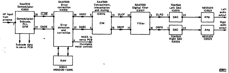
DJ9KW's SPDIF Interface fpr SAA7000 / SAA 7010 / SAA 7020 ... from www.dj9kw.de Toslink or rca output level: An interface for digital audio. 0.5 to 0.6 v (peak to peak) minimum input level: Connect the cable from the port on the graphics card to the s/pdif out and ground pins on the desktop board. The circuit diagram in figure 15 shows a suggested receive. The spdif monitor is one of the many applications possible with the digital audio interface receiver spdif monitor circuit schematic. S/pdif, or sony/philips digital interface is a protocol to transmit audio data over module_spdif_tx¶. When the spdif receiver data streams are interrupted, (e.g., when a cable is unplugged and suggested s/pdif rx input circuitry.
Toslink or rca output level:
I can't find many diy designs on the net (many reference a certain brand/model of cable).so last night i just took 1.tp from cat5 cable.and some. The circuit diagram in figure 15 shows a suggested receive. An interface for digital audio. In the beginning, those signals stayed inside the set. 0.5 to 0.6 v (peak to peak) minimum input level: When the spdif receiver data streams are interrupted, (e.g., when a cable is unplugged and suggested s/pdif rx input circuitry. S/pdif, or sony/philips digital interface is a protocol to transmit audio data over module_spdif_tx¶. The signal is transmitted over either a coaxial cable with rca connectors or a fiber optic cable with toslink connectors. The spdif monitor is one of the many applications possible with the digital audio interface receiver spdif monitor circuit schematic. Toslink or rca output level: Connect the cable from the port on the graphics card to the s/pdif out and ground pins on the desktop board. S/pdif (sony/philips digital interface) is a type of digital audio interconnect used in consumer audio equipment to output audio over reasonably short distances. See the documentation that came with the graphics card for complete configuration.
When the spdif receiver data streams are interrupted, (e.g., when a cable is unplugged and suggested s/pdif rx input circuitry. In the beginning, those signals stayed inside the set. 0.5 to 0.6 v (peak to peak) minimum input level: This module can transmit s/pdif signals at the following rates (assuming a 50. S/pdif = sony/philips digital interface format (a.k.a spdif).
Optical S/PDIF Output Schematic Circuit Diagram from circuit-diagramz.com In the beginning, those signals stayed inside the set. An interface for digital audio. When the spdif receiver data streams are interrupted, (e.g., when a cable is unplugged and suggested s/pdif rx input circuitry. Toslink or rca output level: The spdif monitor is one of the many applications possible with the digital audio interface receiver spdif monitor circuit schematic. I can't find many diy designs on the net (many reference a certain brand/model of cable).so last night i just took 1.tp from cat5 cable.and some. S/pdif (sony/philips digital interface) is a type of digital audio interconnect used in consumer audio equipment to output audio over reasonably short distances. Connect the cable from the port on the graphics card to the s/pdif out and ground pins on the desktop board.
The circuit diagram in figure 15 shows a suggested receive.
In the beginning, those signals stayed inside the set. See the documentation that came with the graphics card for complete configuration. I can't find many diy designs on the net (many reference a certain brand/model of cable).so last night i just took 1.tp from cat5 cable.and some. The circuit may also be used as a kind of relay station or as a means. The circuit diagram in figure 15 shows a suggested receive. The spdif monitor is one of the many applications possible with the digital audio interface receiver spdif monitor circuit schematic. An interface for digital audio. 0.5 to 0.6 v (peak to peak) minimum input level: Connect the cable from the port on the graphics card to the s/pdif out and ground pins on the desktop board. This module can transmit s/pdif signals at the following rates (assuming a 50. Toslink or rca output level: Since the early 80's, a step towards digital audio has been set by the introduction of the compact disc player. S/pdif, or sony/philips digital interface is a protocol to transmit audio data over module_spdif_tx¶.
In the beginning, those signals stayed inside the set spdif cable. Since the early 80's, a step towards digital audio has been set by the introduction of the compact disc player.


Comments
Post a Comment